D. Bompadre – A. Rachini (Rigel S.p.A.)
When talking about a particle monitoring system, it is important to consider all its components, including those that apparently could play a marginal role but which actually contribute significantly to determining its performance characteristics. This article focuses in particular on the connections that join the isokinetic probe to the particle counter, often referred to as “particle transmission lines”.
Introduction
Continuous particle monitoring is a system used in many industries, from the manufacturing of pharmaceutical and electronic devices to the healthcare and aerospace industries, to constantly monitor the degree of cleanliness of controlled contamination areas.
In this particular moment, we are experiencing a transition phase of particle monitoring, strongly stimulated by the issue, in 2015, of the ISO 14644-2 standard. The innovation is focused, in particular, on the ability to intercept any possible adverse event of a short duration or even impulsive, which could jeopardize the quality and safety of the particular processed product and / or of the patient’s health.
It is therefore evident that the functional characteristics of a monitoring system are of fundamental importance to meet the regulatory requirements: the characteristics of the particle counters are important, as are those of the applications that manage the system, as they are essential components.
However, we must also consider that a monitoring system is quite complex and there are many components, some of which could also appear of marginal importance, which instead play a decisive role, as they contribute significantly to determining the performance characteristics of the entire system.
These include the connections that join the isokinetic probe to the particle counter, often referred to as “particle transmission lines”.
Ideally, such lines should hardly exist: the isokinetic probe should in fact be located exactly above the particle counter, and therefore no significant distance should be traveled from the sampling point to the reading point located inside the particle counter. In reality, however, it is often necessary to consider various structural constraints that prevent the positioning of the particle counter close to the critical point defined by the risk analysis. Here, then, we are forced to create a particle transmission line.
The regulatory context
The regulatory context, essentially made up of GMP guidelines and ISO standard, has a moderate level of detail, which has not favored the formation of a unique school of thought, derived from the experience accumulated over the years by who had worked on the problem.
The GMP Annex 1 guideline currently in force, issued in 2008 and currently under review, contains a generic, rather obvious, indication. In fact, it states in paragraph 11:
“Where remote sampling systems are used, the length of tubing and the radii of any bends in the tubing must be considered in the context of particle losses in the tubing.”
In the draft of the new guideline Annex 1, this generic indication has disappeared, probably in compliance with the principle, available both in this document and in its predecessor, according to which:
“This guidance does not lay down detailed methods for determining the microbiological and particulate cleanliness of air, surfaces etc. Reference should be made to other documents such as the EN/ISO Standards and Pharmacopoeial monographs for more detailed guidance”.
As for the ISO standards, an indication can be found in the ISO 14644-1: 2015:
“The transit tube from the sampling probe inlet to the LSAPC sensor should be as short as possible. For sampling of particles larger than and equal to 1 μm, the transit tube length
should not exceed the manufacturer’s recommended length and diameter, and will typically be no longer than 1 m in length.”
These are fairly precise design guidelines that challenge the particle counter supplier’s recommendations and stipulate that the sampling line must be no longer than one meter.
It is clear that the length, as well as the diameter, cannot be the only parameters that come into play. Another element of great importance is the geometric shape of the connection, and in particular, as also indicated in Annex 1, the radius of the curves. This will inevitably be specific to each specific installation; that is, it will not be a project datum, such as length or diameter, but will be the result of compromises due to installation constraints.
Therefore, the experimental tests assume a fundamental importance, through which to ensure that each installation does not involve a significant loss of efficiency in the counting, in particular, of particles with a diameter larger than 5 μm.
From this point of view, the 2010 PIC / S guide may partly come to our supports, as it is aimed at providing control bodies with practical indications with the goal of harmonizing the content of aseptic production inspections. In this guide, you can find in paragraph 11:
“This section addresses concerns especially for the sedimentation of 5 μm particles in remote systems (as a rough example, s-shaped bent tubing of 1.5 m length can already absorb about 30% of the 5 μm particles.). The company must qualify their particle
sampler and sampling system for both particle sizes, 0.5 μm and 5 μm.”
Here the indication to perform experimental tests is very clear, for which the word “qualify” is even used.
In conclusion, the subject of the efficiency of particle transmission lines is significantly present in various documents.
However, it could also be summarized that, even more than the specific references – which are anyway present – the very nature of particle monitoring requires a careful analysis of the issue.
As a GMP guideline, the new Annex 1 draft indicates that “The grade A zone should be monitored continuously” … “so that all interventions, transient events and any system deterioration would be captured and alarms triggered if alert limits are exceeded.” The above implicitly requires that the measure provided by the system is indisputably reliable — which it could not be if it were penalized by the inefficiency of particle transmission lines.
Design choices
Design choices can be well identified by combining indications provided by standards with those by the manufacturers.
In the design choice related to the length of the transmission lines, there is no reason to deviate from the indications of ISO 14644-1: 2015, which recommend not to exceed one meter in length.
As to materials, stainless steel can be used, or even a particular tube, the Bev-a-Line, recommended by all manufacturers of particle counters. This tube consists of an internal core with a very low roughness coefficient, coated by a sturdy outer shell from which it is totally inseparable, and can be sterilized in an autoclave. Particular attention should be paid to the creation of transmission lines that systematically avoid any type of roughness, and free of tight curves.
Experimental verifications
As stated earlier, the geometric shape of particle transmission lines inevitably comes into play as a result of compromises made during installation. This makes an experimental confirmation test inevitable: the problem arises of how to carry out this verification.
In the sampling line path leading from the isokinetic probe to the particle counter, the concentration and particle size distribution of the materials contained in the air sample can be subject to modifications due to various alteration processes of contaminating elements’ contents.
These processes depend on various factors, namely:
- the diameter of the particles;
- the sampling line fluid dynamic conditions;
- the sampling line geometry;
- the material from which the walls of the sampling line itself are made.
Such particle loss processes may occur in different ways, summarized as follows:
- loss due to diffusion;
- loss due to electrostatic effects;
- loss due to sedimentation;
- loss due to inertial effects.
All the above suggests to analyze these phenomena macroscopically and then to undertake a transfer efficiency evaluation process. It is therefore possible to identify, in each monitoring point P, a quantity E
transf(dp) which varies as a function of the particles’ diameter.
Under optimal operating conditions, i.e. in the absence of transfer lines, it is normal to expect the E
transf(dp) value to be substantially uniform across the particle size range of interest.
In this case, therefore, it is sufficient that the particle counter is kept calibrated with counting efficiency and the suction flow rate is kept within the limits established by ISO 21501-4 to conclude that the data are adequately representative of the area under investigation. Conversely, when it is not possible to use the optimal configuration, but is suggested to use a transfer line, the value of E
transf(dp) should be < 1. Determining E
transf(dp) is therefore essential to have a measure of the reliability of the particle count.
The verification methodology provides for the execution of several consecutive samplings with two reference particle counters in two different configurations:
- in the first configuration (Equivalence Configuration), the two instruments A and B work in parallel, sampling at the same sampling point. This configuration is used to verify that tools A and B are experimentally equivalent; it is also essential to assess the statistical uncertainty of the experimental efficiency data (see Figure 1a);
- in the second configuration (Test Configuration) instrument B is connected to the transfer line under test while sensor A is left in the optimal configuration (see Figure 1b).
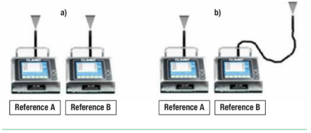 Figure 1 – Sampling with Two Reference Particle Counters in Equivalence Configuration (Figure 1a) and Test Configuration (Figure 1b).
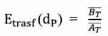
The transfer efficiency of the lines can be determined using the average particle concentration obtained during the Test Configuration of the transfer line under consideration. In fact, indicating with AT and BT (
 ) the average concentration values measured during the Test Configuration, the transfer efficiency Etransf(dp) is defined by the ratio:
From an experimental point of view, the significance of this value, determined for each individual monitoring point P, acquires consistency when a relative uncertainty value is associated with it. For this reason, before running tests in the Test Configuration, they are run in the Equivalence Configuration – which in fact allows to assess uncertainty.
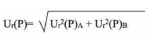
The relative uncertainty U
Er(P) is calculated from the relative uncertainty associated with each particle counter (Ur(P)A for the particle counter A and Ur(P)B for the particle counter B):
U(A) and U(B) are absolute uncertainties, while AE and BE (

) are the experimental concentration data measured during the Equivalence Configuration — values practically identical since the two particle counters are equivalent.
It can therefore be concluded that:
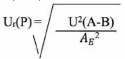
or
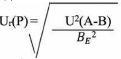
where:

is the population variance A-B

is the average squared value
Results evaluation
Experimental evidence provides a clear and unambiguous measure of the correctness of the particle transmission lines.
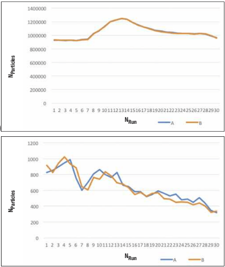
The following two graphs, the first related to particles of size> 0.5 μm and the second to particles> 5 μm, clearly show the behavior of a transmission line with an efficiency that does not alter the correct count.
Conversely, the next two graphs show the behavior of a transmission line determining an important alteration regarding the count of particles with size > 5 μm.
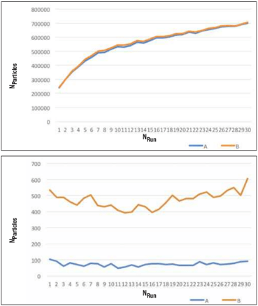
The loss of efficiency is of such relevance to make the monitoring of macroparticles unreliable. If the point in question were in a Grade A environment (according to GMP Annex 1), in which the population of macroparticles is extremely low, the consequence would be the substantial non-significance of a monitoring action at that point, due to particle loss along the sampling line.
Conclusions
It has been shown how the particles transmission lines may penalize the effectiveness of particle counting by in fact creating a path, with various lengths and shapes, within which it is possible the sedimentation of a certain number of particles, that therefore will not reach the particle counter. This aspect is particularly important for large particles (i.e. with a diameter > 5 μm), both because they are more subject to sedimentation, and because their population is particularly lower than those > 0.5 μm, and consequently even small variations can significantly alter their count. It is therefore of fundamental importance to accurately assess the impact of the particle transmission lines on the effectiveness.
The evaluation must be first carried out in the design phase, in the choice of materials, length and shape of the transmission lines. Subsequently, it is also necessary to experimentally verify the quality and adequacy of the design choices made by validating the particle sampling process.
Bibliography
Atmos. Meas. Tech: Particle Loss Calculator;
CLIMET INSTRUMENTS COMPANY: Best Practices non-viable Monitoring Application Note: 161808C;